DTC P0161 HO2S Heater Performance
Bank 2 Sensor 2

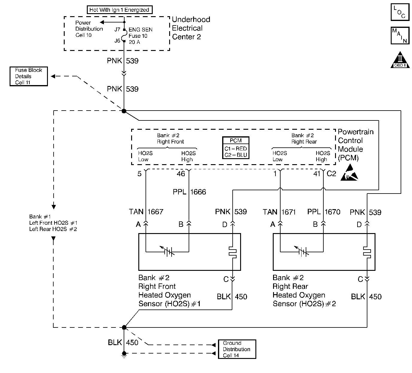
The PCM supplies a bias
voltage (approximately 450 mV) on the Heated Oxygen Sensor (HO2S) signal
high and low circuits. When you turn the ignition to the ON position, battery
voltage is supplied to the HO2S heater. As the heater reaches the operating
temperature, the HO2S voltage responds by changing from a bias voltage range to
the normal operation. Typically, as the HO2S reaches the operating temperature,
the HO2S voltage goes from a bias voltage to a voltage below 300 mV.
Depending on the exhaust gas content, it is possible for the HO2S voltage to go
above 450 mV.
The PCM runs the heater
test only on a cold start (depends on the cumulative air flow) and only once an
ignition cycle. When you start the engine the PCM monitors the HO2S voltage.
When the HO2S voltage goes above or below the bias range threshold, the PCM
determines how much time it took. If the PCM detects that the process took too
much time for the HO2S to enter into normal operating range, a DTC sets. The
time the process takes the HO2S to reach operating temperature is based on the
amount of air that flows into the engine.
Conditions
for Running the DTC
- DTCs P0101, P0102, P0103, P0112,
P0113, P0117, P0118, P0121, P0122, P0123, P0125, P0335, P0336,
P0351-P0358, P1258 not set.
- The intake air temperature and the
engine coolant temperature are less than 50°C (122°F) and are within 8°C
(14.5°F) of each other at engine start-up.
- The ignition voltage is between
10.0 volts and 16.0 volts.
- The engine air flow is less than
30 g/s.
- The AIR, EGR, and the Catalyst
diagnostics are not active.
Conditions
for Setting the DTC
The HO2S voltage remains
between 300 mV and 700 mV for a predetermined amount of time (depends
on engine coolant temperature and air flow).
Action
Taken When the DTC Sets
- The PCM illuminates the malfunction
indicator lamp (MIL) on the second consecutive ignition cycle that the
diagnostic runs and fails.
- The PCM records the operating
conditions at the time the diagnostic fails. The first time the diagnostic
fails, the PCM stores this information in the Failure Records. If the
diagnostic reports a failure on the second consecutive ignition cycle, the
PCM records the operating conditions at the time of the failure. The PCM
writes the conditions to the Freeze Frame and updates the Failure Records.
Conditions
for Clearing the MIL/DTC
- The PCM turns OFF the malfunction
indicator lamp (MIL) after 3 consecutive ignition cycles that the
diagnostic runs and does not fail.
- A last test failed, or current DTC,
clears when the diagnostic runs and does not fail.
- A history DTC clears after
40 consecutive warm-up cycles, if no failures are reported by this or
any other emission related diagnostic.
- Use a scan tool in order to clear
the MIL and the DTC.
Important
- Remove any debris from the PCM connector surfaces
before servicing the PCM. Inspect the PCM connector gaskets when
diagnosing/replacing the PCM. The gaskets prevent contaminate intrusion
into the PCM.
- For any test that requires probing the PCM or a
component harness connector, use the Connector Test Adapter Kit J 35616-A .
Using this kit prevents damage to the harness connector terminals.
- Using the Freeze Frame and/or Failure
Records data may aid in locating an intermittent condition. If you cannot
duplicate the DTC, the information included in the Freeze Frame and/or
Failure Records data can help determine how many miles since the DTC set.
The Fail Counter and Pass Counter can also help determine how many
ignition cycles the diagnostic reported a pass and/or a fail. Operate the
vehicle within the same freeze frame conditions (RPM, load, vehicle speed,
temperature etc.) that you observed. This will isolate when the DTC failed.
- The heater diagnostic will only run
on a cold start and run once per ignition cycle.
- An oxygen supply inside the HO2S is
necessary for proper operation. The HO2S wires provides
the supply of oxygen. Inspect the HO2S wires and connections for breaks or
contamination. Refer to Heated
Oxygen Sensor (HO2S) Wiring Repairs in Wiring Systems.
- For an intermittent condition, refer
to Symptoms
.
The numbers below refer
to the step numbers on the diagnostic table.
- The engine must be
allowed to cool, as the HO2S may be at operating temperature and no drop
or rise in HO2S voltage would occur. If the HO2S voltage stays between
300-700 mV indicates the HO2S heater is inoperative. For any test
that requires probing the PCM or a component harness connector, use the
Connector Test Adapter Kit J 35616-A .
Using this kit prevents damage to the harness connector terminals.
- Lower the exhaust
system to gain sufficient access to the HO2S and/or the HO2S connector if
necessary. Refer to Catalytic
Converter Replacement in Engine Exhaust. This step verifies whether
the B+ supply is available at the sensor.
- Inspect the ignition
feed circuits at the
|
Step |
Action |
Value(s) |
Yes |
No |
|
Did
you perform the Powertrain On-Board Diagnostic
(OBD) System Check? |
-- |
|||
|
Important If you have been operating
the engine, allow the engine to cool for about one half hour before
proceeding.
Does
the HO2S voltage go from a bias voltage to above or below the specified
values? |
300-700 mV |
Go to Diagnostic Aids |
||
|
Inspect
the fuse for the HO2S ignition feed. Is the HO2S fuse open? |
-- |
|||
Is
the test lamp illuminated? |
-- |
|||
|
Connect
the test lamp J
34142-B between the HO2S ignition feed and the HO2S heater ground. Is the
test lamp illuminated? |
-- |
|||
|
Measure
the resistance between the HO2S ignition feed and the HO2S heater ground at
the HO2S pigtail using the DMM J 39200 . Is
the HO2S resistance within the specified values? |
3.5-14.0ohms |
|||
|
Repair
the open in the HO2S ignition feed circuit to the HO2S. Refer to Wiring
Repairs in Wiring Systems. Is the action complete? |
-- |
-- |
||
|
Repair
the open in the HO2S heater ground circuit. Refer to Wiring
Repairs in Wiring Systems. Is the action complete? |
-- |
-- |
||
Did
you find and correct the condition? |
-- |
|||
|
Replace
the HO2S. Refer to Heated
Oxygen Sensor (HO2S) Replacement - Bank 2 . Is the action complete? |
-- |
-- |
||
Is
the action complete? |
-- |
-- |
||
Does
the scan tool indicate that this test ran and passed? |
-- |
|||
|
Select
the Capture Info option and the Review Info option using the scan tool. Does
the scan tool display any DTCs that you have not diagnosed? |
-- |
Go to the applicable
DTC table |
System OK |